Sensors and Switches
FP-657706-K07
Fig. 1: Conductor in front of electronics has slipped
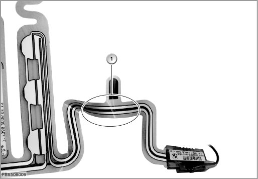
Index / Description
1 Conductor has slipped
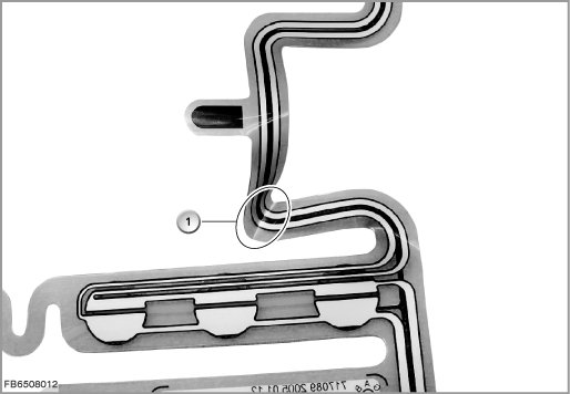
Fig. 2: Conductor tracks on transverse seams slipped
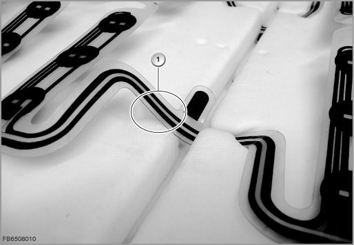
Index / Description
1 Conductor has slipped
Fig. 3: Cast electronics box is displaced or raised
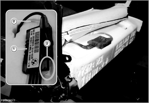
Index / Description
1 Electronics box
2 Electronics box has slipped
Fig. 4: Use cloth adhesive tape to attach the electronic component into the recess of the seat cushion
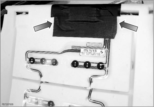
Fig. 5: Seat occupation mat is kinked
Index / Description
1 Conductor track twisted
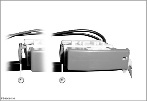
Fig. 6: connector not correctly snapped in and not correctly locked in the bracket of the base springs
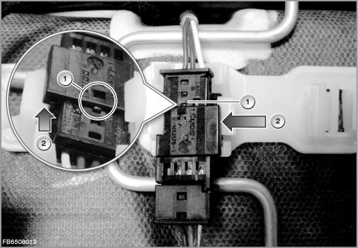
Index / Description
1 Connector not locked in place
2 Connector not correctly locked in place in the bracket of the base springs
Fig. 7: connector correctly snapped in and correctly locked in the bracket of the base springs
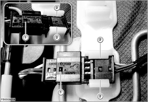
Index / Description
1 Connector locked in place correctly
2 Connector locked in place correctly in the bracket of the base springs
Fig. 8: Secure the central seat connector with cable ties
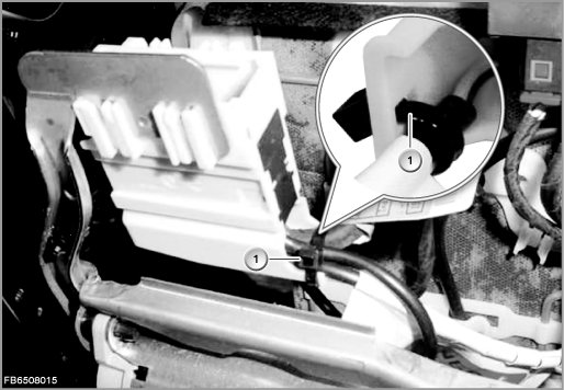
Index / Description
1 Cable tie
Fig. 9: Locking of central seat connector
Index / Description
1 Slider not locked in position
2 Slider locked in position